Note:
This is a copy of an article that I wrote and was published in Popular Electronics magazine back in 1987. Popular Electronics magazine has been out of business for many years now.
Improve Reception on the Lower Frequencies
With A Low Cost Loop Antenna
By
Dave Hollander N7RK
Introduction
One of the greatest problems encountered when one likes DXing on the lower frequencies such as 1.8 and 3.5/3.8 Mhz is weak signal reception. This problem is compounded when one lives in a noisy location. Power line noise can be a real deterrent and in many cases may even give second thoughts about ever working DX on the lower bands. A recent move to a new location allowed me to return to my favorite DX band; 80/75 meters. I put up a pair of phased verticals (Hy Gain HyTowers) and despite having underground utilities was quite shocked to find an almost constant S9 noise level on 80 meters. This noise was coming from power lines a couple of blocks away. Although the power companies have been cooperative, a alternate receiving antenna was necessary as it can sometimes take them weeks, even months to fix the problems and you never know when the noise is going to re-occur (usually when a DX-pedition is on from a country you have needed for 15 years!).
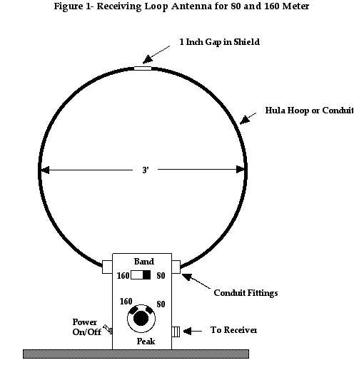
Their have been many schemes for receiving antennas such as outdoor loops of wire, etc. A beveridge antenna would have been ideal however, my backyard is a bit small for that type of antenna. After studying the antenna books, the handbook and various articles1, I decided to build a receiving loop that could be placed inside my shack next to the operating position. Additionally, all of the loop antennas previously described covered only one band. What follows is a very inexpensive indoor receiving loop which covers both 80/75 and 160 meters. Changing bands is accomplished with the flip of a toggle switch. This loop which is quite simple and easy to build shown in figure 1. Let me add that it is also inexpensive and if one is a good scrounger it can probably be built for under thirty dollars.
Figure 1
Circuit Details
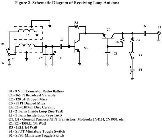
The loop itself is made with a hula hoop which can be purchased at most toy stores. A single turn of insulated wire (wire size is not critical) is placed inside the hula hoop and this is resonated with C1 , a 365 pF broadcast variable capacitor for operation on 80 and 75 meters. For operation on 160, an additional two turns are place in series with the 80 meter coil. S1 adds the additional inductance for 160 and when in the 80 meter position, disconnects that inductance leaving it as an open circuit eliminating mutual coupling. The output of this is fed into a very simple two transistor pre-amp. To eliminate electrostatic noise such as power line noise the loop must be shielded. The schematic of the entire assembly is shown in figure 1. Q1 and Q2 are not critical and can be any general purpose NPN transistors. The assembly is built using point-to-point wiring on a terminal strip which is mounted to the inside of a small minibox. The whole assembly is built around a 2" x 3"x 5" minibox because that is what I had in my junkbox. The box is than mounted to a piece of wood, in my case 1"x12"x12" (I happened to have a piece of wood this size laying around). Power for the loop pre-amp comes from a 9 volt transistor battery which is mounted inside of the minibox. Current drain is so low that this should last at least a year provided you remember to turn it off after an operating session. An alternate power source would be an inexpensive wall charger providing between 6 and 12 volts. Operating voltage of the pre-amp is not critical.
Loop Construction Details
Although I mentioned using a hula hoop, the loop can also be build with electrical conduit. This is fine if one has the facilities to bend it. An easier way is by wrapping a hula hoop with tin foil and securing it by wrapping the loop with electric tape. The diameter of the loop is approximately three feet and this is not a very critical dimension. the hula hoop is cut and the ends are brought into the minibox through electrical conduit fittings which are mounted to the sides of the minibox. When wrapping the hoop, leave about an inch of aluminum foil on each end exposed as this will be used to make electrical contact with the minibox. The hula hoop may be slightly undersized for the conduit fittings and may need to be shimmed. I used some 10 mil copper strips wrapped around the tin foil. After assembling the shielded hula hoop to the box, pass one turn of wire through the loop and into box and connect it to to C1, the other end goes to S1, (see Figure 2). This is the 80 meter section. Than take another piece of wire and pass two turns through the inside of the loop and hook it to S1 and the other end to ground (see figure 2). This is the 160 meter section.
Figure 2
Operation
Operation of this loop is very simple. Connect the loop to the antenna jack on your receiver or to an auxiliary antenna port on your transceiver. If your transceiver does not have an auxiliary antenna jack you will have to build some type of antenna switching arrangement. Transmitting into the loop will destroy the transistors in the pre-amp. Turn the loop on and set the switch to 80 meters. Adjust C1 until the noise level peaks up. You should now hear signals by tuning around the band. If you have power line noise, rotate the loop until their is a null in the noise. The null will be very sharp. In some cases the noise can be dropped from an S9 to S0. The loop can also be used to lower extremely strong signals from local amateurs. The loop does have limitations. If their is more than one source of noise, the loop will not be effective. When using the loop on 160, you may have several false peaks when adjusting C1. The correct setting is determined experimentally. The correct peak will be obvious. With the incorrect settings, you will hear all kinds of broadcast garbage. The loop can also be used to lessen the high QRN from thunderstorms. By rotating it away from the direction of the storm, the QRN level is lowered several S-units which may make the difference between good copy and no copy at all.
1 Boothe,Weak Signal Reception on 160-Some Antenna Notes, QST for June 1977
Copyright © 2009 by David S. Hollander
All materials contained within these pages
All Rights Reserved.